Post #14 - TETRIS in ABAQUS – Part 3
This third article on the mini-project I set myself, to build a version of TETRIS in ABAQUS, focuses on creating the game elements and manipulating the user’s view.
The original game was completely 2D, this version appears to be 2D, but it is actually 3D, with the view controlled so that there is no perspective. The visual elements of the game are divided between creating the objects that represent the playing pieces and the playing surface, and control of the view, screen setup and orientation. Both of these areas have applications in more usual uses of ABAQUS!
Screen Setup
ModelAndVp
Most of the routines that will follow make use of a helper function that returns the current model and viewport. As it stands the function only has two active lines, Figure 1. This seems over complicated, but it means that if you wish to rename the model there are only two places in the code to change the name and if you wish to edit the code to use the current model you only have to add a couple of lines in one place. It is almost always a good idea to put repeating code into separate functions rather than have multiple locations to edit.

SetupView
This function aligns the viewport, limits the range of the camera view and defines how the parts are being displayed.
The game is made up of lots of blocks, each an instance of a block prototype. Displaying using default settings would show both the block and the play area as one colour. Not terrible, but not pretty. Colouring by instances would be very confusing since every block instance would be a different colour. So, I decided to display by material, creating two dummy materials, see below, one for the blocks and one for the play area, and use the default colours for each, this is shown in the section highlighted in purple in Figure 2.
Fixing the view so that the user gets a 2D image to work with and cannot see the edges of the play area is done by creating a custom view and storing this in one of the user defined views, see the yellow section below.
The playing area is 30 units long, by 9 high. Both parts, the block prototype, and the play area, are generated on the Z=0 plane. The view width and height are set to be slightly bigger than the play area, with the camera positioned at the centre of the playing zone, at a suitable distance, (15,4.5,10), the camera target is a point along the Z-axis from that location, at the mid-height of the parts (15,4.5,0,5). Note that autofitting of the assembly in the view has been turned off, to ensure that the play area margin extends out of view, and that perspective has been removed by setting the projection to parallel. The assembly is displayed to show the playing area and as many block instances as exist.

Format Screen
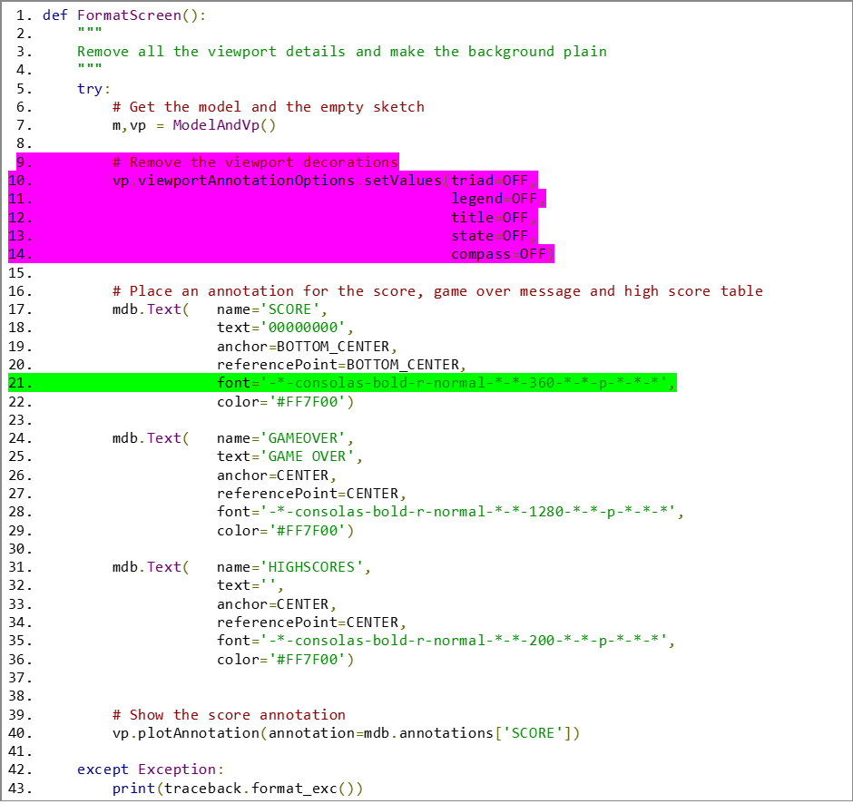
In this section we shall remove all the standard viewport annotations and prepare the game annotations for the score, the game over banner and display of high scores.
Viewport annotations can be turned on or off very simply using the setValues function, see the section highlighted in purple. This is also the route in if you wish to customise these annotations, e.g. change the fonts.
The game annotations are all true annotations and are fixed to the screen, essentially 2D, as shown in Figure 3. You can also have annotations tied to 3D locations, so they move with the model, or some combination of the two. As such, these are the simplest type and also the most appropriate to this case.
All of the annotations are placed with respect to named default positions, given by constants, e.g. CENTER. The anchor point is the screen location. The reference point is the region on the text box which is tied to the anchor point. Offsets have not been applied since in this case it was not necessary.

Three annotations have been created in advance. They are given default text values that will be replaced as the game goes on and they are shown. Only the default score is initially displayed.
The format string for the fonts is very specific, green highlight, and you must respect it. The font size is given by the large number, so 360 gives a 36 pt font, 1280 is 128pt etc. Consolas is the font name, I wanted a monotype font since this made the layout of the leaderboard annotation easier. Some care in font choices is needed because not all fonts get rendered by ABAQUS. Bold covers the font weight and normal could be replaced with italic. The apparently random collection of dashes and stars matter, in that if they are wrong you will get errors, so be careful when you make changes to the font string.
Return Screen
Once the game is over the screen should be returned to the default working settings and the annotations removed. Note that in this function, Figure 5, the model itself has already been removed so the reference is only to the current viewport, to access the annotations.

Physical Setup
The physical parts for the game are made up of the playing area and a series of shapes, created from patterns of unit cubes. These are geometrically very simple objects with some extra features that make the game easier to code. These parts are assigned dummy materials to enable them to be displayed as consistent colours in the assembly.
Materials
In this instance the materials and sections are dummies to aid display so they only need to exist, they do not need to be meaningfully populated with properties, see Figure 6.

Play Area
The play area is a frame, one unit deep, that is larger than the screen view, Figure 7. It has a rectangular hole in it for the playing area. It is assigned the section Section-Wall. At the far right-hand side the wall surface is partitioned into unit squares, making a regular grid. This is so that each of the faces in that end surface can be queried for its centroid. A list of face centroid values is maintained to determine when blocks are in contact. This will be more fully explained in the last post of this series.

The basic shape is defined in the sketch, purple highlight Figure 8, and extruded to unit depth. In the yellow section, the dummy material is assigned for display purposes. A single instance of the play area is created in the assembly, green highlight. The inner open area starts at (0,9) top left and ends at (30,0) for the bottom right. This will be centered in the view by the camera settings discussed above.
Partitioning the end wall, cyan highlight, is done using a sketch on the end wall face, face 6 in the original unpartitioned part. The sketch is transformed onto that face, and the sketch is centred on the middle of the face. Lines are drawn across the face to subdivide it to match the playing grid.
Finally, a surface is created, grey highlight, that covers the end of the playing field. All the faces within that surface are looked at and their centroids are found and stored in a list for future use. Two lists are held, one contains the face centroids, the other a name for the object that contains it. It would have been better to build a list of tuples that kept this information paired.

Creating Shapes
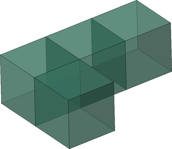
The shapes, in keeping with the original, are just patterns of cubes. This allows rows to be created from collections of cubes rather than determining which bit of complete shapes is involved.
Cube Part
Cube creation is very simple. A square sketch, with unit sides, centered on (0,0) in the X-Y plane, is given a unit depth extrusion in the Z-direction, purple highlight, Figure 9. A suitable dummy material is allocated to the part, yellow highlight.

Shape Creation
Shapes are built up from collections of cubes. They are predefined collections with the data held in the customData area. This data is setup in an initialisation step, Figure 10. This is not essential, but I was playing with other ways of doing this or getting a bit fancier. As it stands this information is stored with the model, a global variable in the kernel module for the list of offsets for the cube centres would have been sufficient. The offsets for each cube instance needed to build a particular shape is shown in the yellow section in Figure 10. This establishes the locations of the blocks with respect to each other, about the assembly origin.

Creating a shape is performed in Figure 11. A shape is picked randomly from this list of possible shapes, and a counter is updated, yellow highlight. If the 15 shapes have been created the time delay between advances down the track will be reduced and the counter reset, grey highlight. The purple section shows how a set of cube instances is created and offset from their creation point to form the shape, and then the whole collection of instances is translated to the starting point in the middle of the top of the track.

The game is now ready to start. A shape is in play and will shortly advance down the track in response to the timer check discussed in Post#13.


Comments